Stationary hand drill press – how does it work?
Welcome! / Forums / General Woodworking Discussions / Tools and Tool Maintenance/Restoration / Stationary hand drill press – how does it work?
Tagged: Hand drill
- This topic has 13 replies, 8 voices, and was last updated 7 years, 3 months ago by
 David R..
-
AuthorPosts
-

Hello friends.
I recently got a simple hand drill press, but I don’t understand a certain aspect of how it works: The shaft goes through the axle of the turning wheel, which means it fixates the wheel, but also prevents it from being turned. How is that supposed to work? I saw other variants which are fixed separately, which makes sense.
Any hints and ideas are appreciated.
Attachments:
You must be logged in to view attached files.Are you referring to the square-headed piece? Does it actually go right through the axle of the big geared wheel or does its tip press against it? It looks to me as if the end would ride in a groove around the axle and keeps it from sliding out of the main casting. Maybe someone has tightened it to much or the machine is frozen up with hardened lubricants.
Dave
I added a few lines for clarifications:
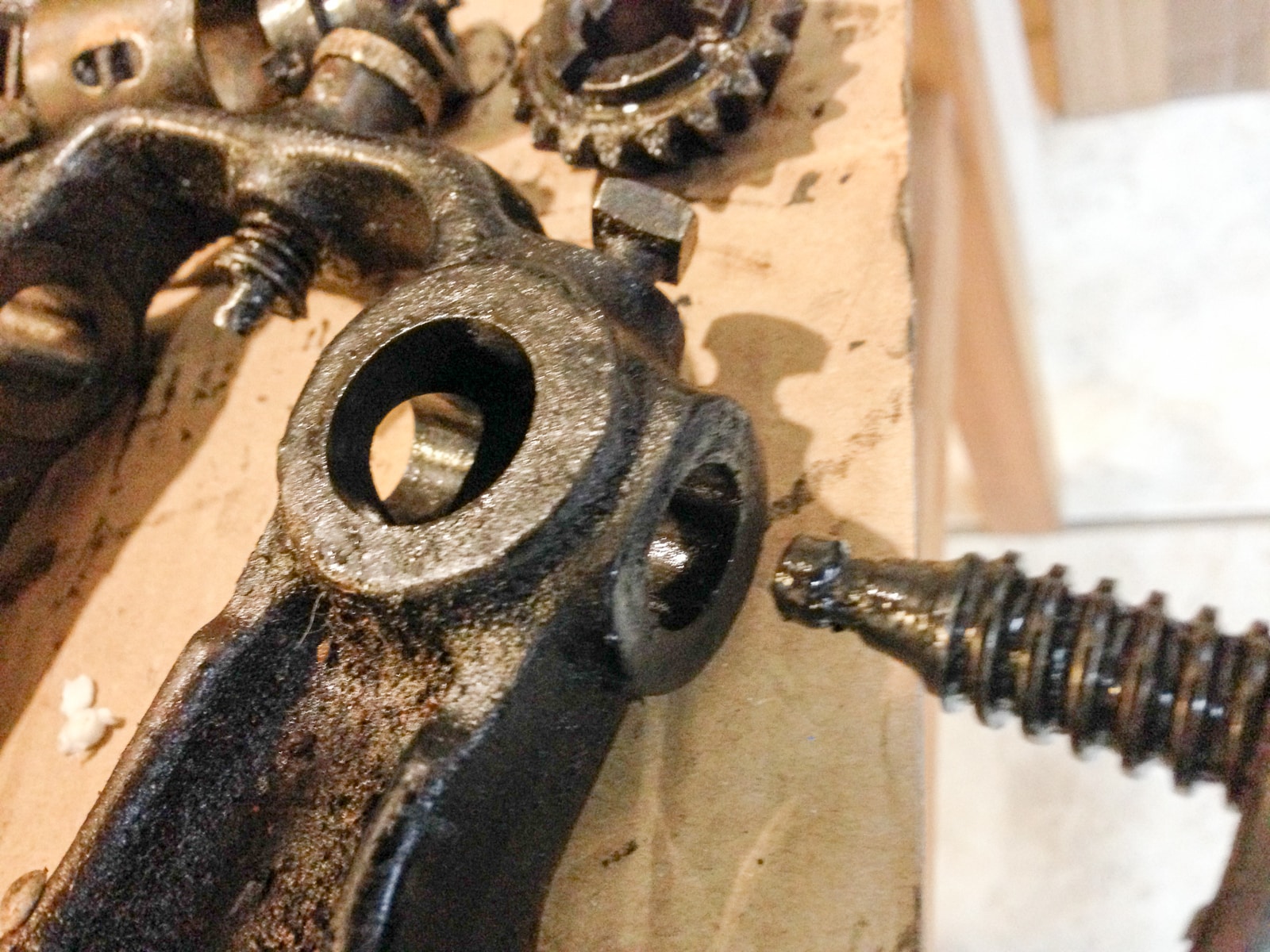
Blue is the shaft or shank of the drill, it is connected to the depth adjustment wheel at the point of the orange arrow. Now the red axle of the wheel has a hole, through which the shank goes through. If so, it cannot turn. I can pull the shank down below the axle, and the wheels will turn, but there is nothing pushing the shank downwards nor keeping it from going back into the hole of the axle when it is aligned.
Attachments:
You must be logged in to view attached files.1 November 2016 at 4:25 pm #142068It looks as if the outer cog assembly drives the chuck for turning the bit.
The inner assembly is more complicated. It looks as if the two inner cogs that are at right angles to each other (perpendicular) would drive the upper part of the shaft and therefore push the shaft down into the work.
The square-headed bolt may simply lock the mechanism in place. Or, it may adjust tension as the shaft turns. The flat knob (that protrudes in the SouthEast direction) and ends inside as a threaded bolt, may either be the real locking mechanism, or it may somehow be involved in driving the shaft down.
My next step would be a thorough cleaning to make sure nothing is jamming the tool, and to improve visibility. You’ll have to do it anyway.
Then, taking pictures as you go, and making notes, take the thing apart slowly. This is worth a few hundred US dollars and worth the effort. Also, you may find images of manually operated drill presses via Google Images. Also, I’ve seen people show off these tools on forums such as lumberjocks.com. Definitely an unplugged shop asset if you can get it working.
Be patient. It took me over two years to find out that a tool from my grandfather’s tool chest is a saw tooth set.
Here’s the Google search. Please feel free to loses sleep tonight 😉
-
This reply was modified 7 years, 5 months ago by
jeffpolaski.
-
This reply was modified 7 years, 5 months ago by
1 November 2016 at 8:56 pm #142100Hi David,
Normally with this type of arrangement only one of the cogs is engaged at any one time, and this is achieved by sliding the brass part up and down, as the different cogs mesh this will alter the ratio. You can see the slot in the brass piece in the centre where you slide it and then lock it in position. It looks like this brass centre piece is a little too large, is it a replacement??? As suggested earlier it needs stripping down and checking out.According to this picture the parts on your drill seem correct.
https://s-media-cache-ak0.pinimg.com/originals/95/6d/34/956d347e42afbcd6f149cf968f315929.jpg
Ricardo,
the one you linked is very similar but with an important difference: notice, how there is an additional brace between handle and wheel, where the wheel can turn. Whereas the drill I have does not have such a pice. I can’t seem to make sense from the shank going through the axle of the wheel. If the shank is lower, the axle is no longer fixed. If its higher, the wheel is blocked.
I’m not so much concerned about the other parts of the mechanism at this time. I first have to find out how the wheel is supposed to turn safely.
David
2 November 2016 at 10:35 pm #142130David,
Here are my guesses.
The vertical rod (blue arrow) passes through the frame bits just as it appears (including the center axis of the crank wheel).
The vertical rod is in two segments that can rotate freely from one another – while maintaining their vertical alignment. This allows the upper portion (pointed to by the gold arrow) to turn with the height adjusting screw, and the lower to turn with the crank wheel and chuck.
Meanwhile, the crank wheel turns on a stub axle off the side of the frame, which we can’t see from this view. It does not pass through the frame, despite appearances. Power is transmitted from the crank wheel to the two cogs. Some complexity behind the bronze/brass fitting selects which cog engages splines on the lower section of the rod to offer two speed ratios for the chuck.
Ratio selection is related to the part going from the hole in the side of the fitting through a branch of the frame, and out to the bronze/brass cap. It’s not clear from the pictures, whether this bit is threaded, or surrounded by a spring but it appears to be capable of some sort of in/out motion.
The square-headed plug threading into the apparent (but fake) crank axle housing probably serves as a lubrication port but may exist to service the connection between the upper and lower sections of the rod.
I’m not familiar with these hand drill presses, and find it interesting that it works with a key-less chuck.
It will be interesting to learn what you find out from further analysis.
Best,
Rick G.
6 November 2016 at 12:40 pm #142224Hi David, on this type of drill the large wheel and the handle are fastened together and rotate on the stationary shaft which is locked into the frame. It is two speed and the selector is that button on that brass? (rusty) piece in the middle of the two pinions. Perhaps both pinions are engaged at the same time so locking the mechanism.
Best of luck, Raymond
I found the time to disassemble the drill once more and take a few pictures. It seems the brass pin is indeed to switch gears by (dis)engaging one of the two small gears determining whether the inner or outer teeth of the turning wheels is used.
It still leaves me scratching my head regarding the concept behind having the main shank going through the axle of the handle/wheel part. I have no closeup of the handle, but on the picture in the first post you can see, that it goes through the large hole visible in picture #3 of this post and the shank crosses this, preventing the wheel from turning.
David
Attachments:
You must be logged in to view attached files.30 November 2016 at 4:42 pm #142800Is there a bearing between the shaft attached to the crank and the crank wheel itself? It seems the only way this could ever work.
Maybe that bearing is seized up?
@jimdunleavy With a little bit of help from some oil, I managed to have the wheel rotate on the axis, i.e. there is no bearing, but it turns on the centre bolt. So it does work. Thanks again for the hint.
Now the problem remaining is, that the main shank where the drill head is attached drops down by itself. There seems to be something broken at the top where the top turn wheel (see picture https://woodworkingmasterclasses.com/wp-content/uploads/2016/11/20161120-2085.jpg) is attached to it. It seems usable, but will be troublesome to use for more than the occasional hole.
David
-
This reply was modified 7 years, 5 months ago by
-
AuthorPosts
- You must be logged in to reply to this topic.